Now the materials are sourced, and you have
calculated all the dimensions of your system, time to start creating your cloud
chamber.
Preparing the components for assembly:
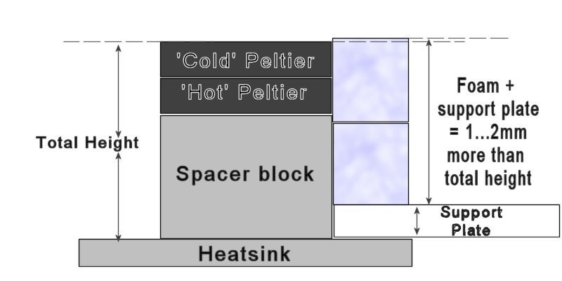
The spacer
block that defines the distance between the heatsink and cold plate
sets the thickness of the closed cell foam used to insulate them.
Total thickness of foam and the support plate will be 1...2mm
thicker than the block height + 2 peltier cells (7mm). This extra
1...2mm thickness allows the cold plate to slightly compress the
foam holding it in place and removing air pockets from between the
layers. This foam insulation can be made from multiple layers of
thinner insulation if 2 or 3 layers of suitably thick foam is not available.
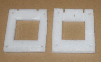
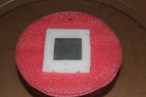
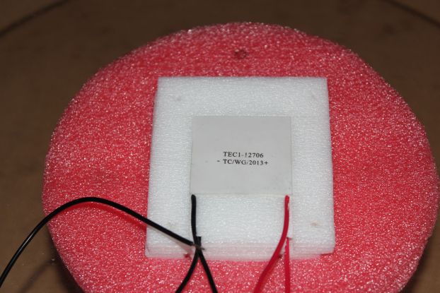
Cut your foam
pieces to be a snug fit around the spacer block and an easy fit
around the peltier cells and approx' 1mm all larger than the
cold plate. eg: If cold plate is 80 x 60 the foam pieces should be
about 81*61, about 0.5mm protruding from each edge. See pic' on right. Any foam
(debris, dust etc) that gets trapped between
the peltiers (even tiny fragments) will cause mechanical stress on
the cell and create a local hotspot. The slight oversize of the foam will create
a snug...almost tight fit between the foam and polystyrene base
insulation.
Cut small channels in the foam for the wires from the peltiers to
exit. Ensure that the wires exit the peltiers straight - do not bend
the wires near their cell connections, they could easily break or
damage the cell. Also cut holes for the nylon fixing screws to pass
through.
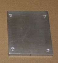
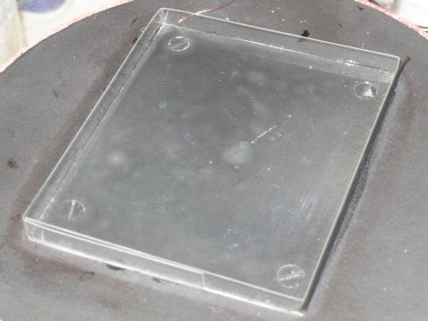
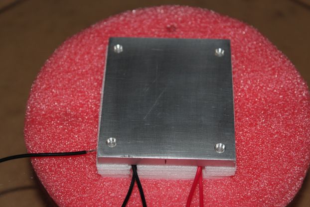
Ensure that
the 'best' side of the cold plate is in contact with the peltiers.
The flatter and smoother the contact surface the better.
4 holes, 3.5mm and countersunk, are drilled into the cold plate.
These are for the nylon screws to fix the cold plate to the spring
bars. Put the holes as near the corners as practical and make the
spring plates to match.
This pic' is before the plate was sprayed with 'calkboard' black
(flat, mat) paint.
Note: Apply several thin layers of spray paint as instructed on
the can but leave the paint to cure in a warm place for SEVERAL
days. The plate gets immersed in pure alcohol at very low
temperatures and any residual solvent in the paint can react and
soften the coating. Do not wipe the painted surface or touch with
anything hard when cold - the paint becomes VERY brittle.
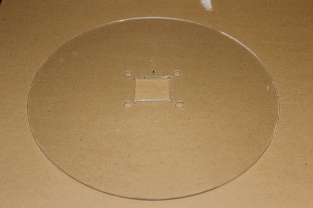
The mounting
plate. 3.5mm perspex. Square hole cut in the centre for the spacer
block, 4 holes cut to pass the 4 nylon mounting screws
though to the spring bars. These holes are larger than the m3 screws
as I had to use extension pillars from the spring plates.
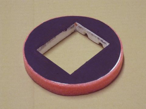
This is a
failed disk (centre hub cracked) from a
wimshurst machine I built.
The support plate needs to be large enough to cover your
watertank (or at least most of it - a small gap is useful for adding
ice or topping up) and be sufficiently stiff to support the system
stably.
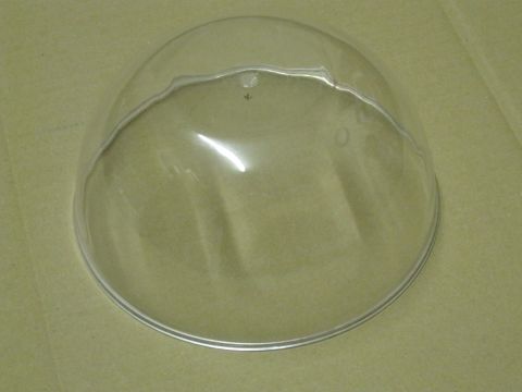
The dome. A
simple perspex 'pudding' bowl. Get a bowl (or similar) that is
'water clear' approx' 15cm diameter and 10cm or so high, try and
avoid ones with large thick rims.
The size is not critical but it
needs to easily clear the corners of the cold plate to leave some
space for insulation. The air next to the dome wall is heated the
most by conduction through that wall. So having 1...2cm gap from the
corner of the plate to the dome wall is desirable.
A perspex 'box' will work but is harder to source.
Glass domes
look great, but glass is a much better thermal conductor than
perspex and will impact the minimum temperatures that can be
achieved.
Cut a disk
from the 20mm (or so) polystyrene sheet to fit loosely in the bottom
of the dome - about 1.5mm gap all round to fit a strip of 2...3mm
foam.
A hole for the cold plate and foam insulation is cut in the
centre of the polystyrene disk. This hole needs to be
approx' 0.5mm larger all round than the cold plate. The foam filler
below the cold plates should be a snug...almost tight fit when the
polystyrene base is fitted. Cut
grooves for the peltier wires to exit.
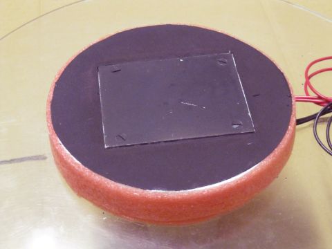
Cut a disk from the black card the same size as the
polystyrene disk and fix, with PVA wood glue, to the top of the
disk, see pic' on right. Leave compressed (card downwards on a flat
surface) for at least 24 hours to allow the PVA adhesive to set.
This card surface must be as flat as possible. It
will bond to polystyrene with PVA glue but not strongly. Cut a hole
in the card matching the coldplate hole in the polystyrene.
Cut a strip(s) of the thin 2...3mm foam sheet and fix to the
outside of the polystyrene disk edge again with PVA glue, see pic' on
right. This
provides a flexible surface for the dome to seal to, the foam
compensating for small errors in the polystyrene disk. This also
protects the polystyrene from damage when the dome is removed and
replaced.
I found that PVA wood glue fixed the foam to the polystyrene
reasonably well.
The fence is
just a strip of thin clear polycarbonate.
Add 5mm (height of the
fence) to the thickness of the cold plate (mine is 6mm thick,
therefore 11mm). Cut a strip of the polycarb' 11mm wide and long
enough to wrap around the cold plate with about 20...40mm overlap. (Plate
60*80 = strip 300mm with 20mm overlap)
Carefully bend the strip so that it fits snugly around the cold
plate with the overlap on one of the short ends.
Shown fitted to the coldplate in pic' on right.
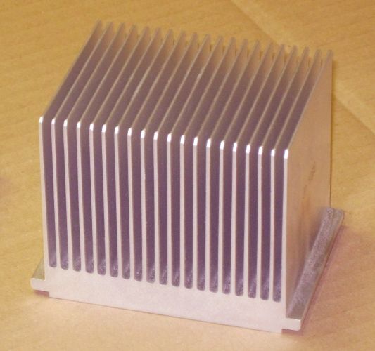
Spring bars.
The design of these will depend upon your heatsink. If you can find
a heatsink with ledges or space for bars to go straight through: pic
right of a heatsink with 'small' ledges. Then straight bars, with cutouts if necessary will fit.
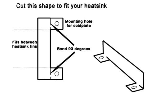
If
your heatsink is 'all fins' then cut 2 spring bars so that the ends
can be folded to provide lands for the screw fixings. See sketch
right.
These spring bars should be made of steel, however
aluminium will work - it's just not very 'springy'.
When
tightening the coldpate screws:
Steel spring plate: Tighten
until screws feel tight, steel (if thin) will bend very slightly.
Aluminium 'non-springy' plate: Tighten the coldplate screws until the
aluminium (if thin, less than 1mm) just starts to 'give'. If the
screws are not at least showing reasonable resistance (tightness) when the plate starts to
give the aluminium too soft or too thin/narrow.
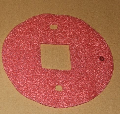
Lower foam
protector. Cut a disk of the 2...3mm foam the same size as the
polystyrene disk. Cut a hole in the centre for the aluminium
block. Cut 4 holes to align with the nylon fixing screws. Cut 2/4
holes for the heatsink to mounting plate screws.
Pic' on right shows disk
before holes for the nylon screws were cut. 'O' is for orientation.
I only have 2 screws to fix the mounting plate to the heatsink.
This adds one layer of insulation and also provided space for the
heatsink...plate mounting screw heads.
Fix the heatsink (flat side up) to a
worktop/bench/vice so as to provide a stable platform for the build.
.Ensure the area is clean/dust free. All mating surfaces (heatsinks,
spacers, mounting plate) must be spotless to prevent bad contact between
the various components.
'Run through this
procedure and dry' fit all the
components together separately to ensure that they fit properly.
Check that the nylon screws are long enough to fix the assembly. Use
threaded spacers if sufficiently long screws cannot be found.
Have some thermal paste available - only a small amount will be
required - and a plastic/wood spatula to spread the paste. A metal one
will damage the aluminium surfaces. Do not use the highly popular 'pea'
or 'blob' methods shown online / youtube - these are NOT manufacturers
recommended practice and you will end up with thick (and therefore
unstable) and uneven thickness resulting in less effective thermal
connections.
If a spacer block is used apply a very small
amount of thermal paste to the side that will mate with the heatsink. Spread this out with a soft spatula or similar
(a blade will scratch the surface!) Place the block on the correct spot
on the heatsink and, applying light but increasing pressure, work the block in a small
circular pattern. You will feel the change in resistance as the layer of
paste thins out and excess is squeezed out at the edges. We are aiming
for the thinnest possible layer of paste whilst not having any dry
spots.
This is a process worth practicing. When the final assembly is
under way it's better not to guess when it 'feels right'.
Short video on right demonstrates this process but with an old PC
processor.
Fit the mounting
plate onto the heatsink and fix with 2 or 4 machine screws. These should
be 'cheese' head or similar and may need a spreader washer if brittle (perspex!)
materials are used.
Careful not to 'lift' the aluminium block (if
used) whilst settling down the plate. The block can move sideways (a
little)
without problems.
In this image the 'spring bars' are fitted and have
the 10mm nylon threaded standoffs to 'extend' the 25mm screws. The
heatasink I used has excellent flat areas for the bars.
Place over the
aluminium block the 2...3mm foam disk (I used 2).
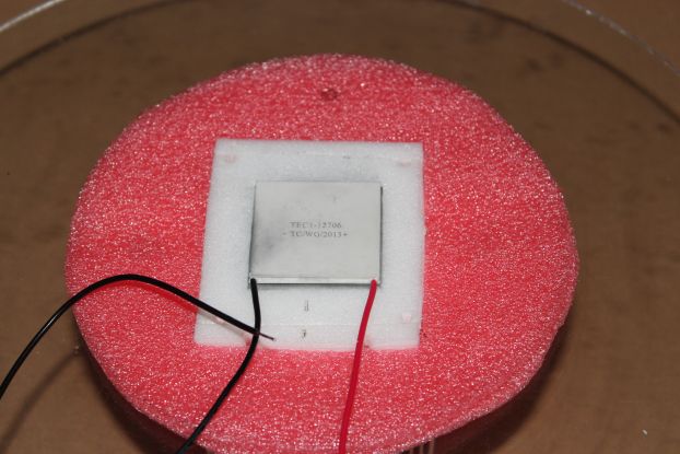
Place over the block the first
piece of foam insulation (or more if you are building up from thinner
layers). The top of the block needs to be clear so we
can 'work' the peltier cell into it.
Apply a very
small amount of thermal paste to the hot side of one peltier cell.
Spread this out with a soft spatula or similar. Place the peltier cell
onto the top of the heatsink/block assembly and, applying light even
pressure, work the cell in a small circular pattern - see
Thermal paste video. You will feel the
change in resistance as the layer of paste thins out as excess is
squeezed out at the edges. We are aiming for the thinnest possible layer
of paste whilst not having any dry spots.
Repeat this process for the
second peltier cell, working it into the top of the first cell. Ensure
that you have the wires exiting on the side you have cut the channels in
the foam insulation.
Loosely fit the
spring bars into the heatsink - hold in place with blutack if necessary.
Fit the final piece(s) of foam insulation over the peltier cells. Ensure
that no stray fibres, particles etc are on the peltier cell.
Apply a very small amount of thermal paste to the top peltier cell.
Spread this out with a soft spatula or similar. Place the cold plate
onto the peltier stack, applying light even pressure, work the plate in
a small circular pattern - see thermal paste
video. The amount of pressure will be larger that the
earlier thermal paste processes since you will also be slightly
compressing the foam insulation - however it's still possible to feel
when the paste has spread sufficiently. Once the paste is evenly spread
keep steady pressure on the cold plate to hold it in place until the
nylon screws are fitted and 'finger' tightened.
Loosly fit the 4
nylon fixing screws through the stack, they should protrude far enough
to be bolted to the spring plates. I fitted 4 x 10mm threaded nylon
pillars to the spring plate - my 25mm screws were too short.
Gently
and evenly finger tighten the 4 screws. The foam must be compressed
whilst these screws are fitted, if the plate lifts up at all from the peltiers it MUST be removed and the thermal paste process repeated.
Once evenly finger tight, tighten each screw in a diagonal pattern no
more than an
eighth of a turn at a time. The plate MUST compress the
peltier stack evenly. Tighten the screws in this fashion until the
spring plates begins to bend - see note
here - or the screws are getting tight.
The tighter the compression the more effective the thermal contacts,
nylon screws are a compromise as they limit the pressure to a few Kg,
but their thermal properties outway that limitation.
If the cut channels for the peltier wires are a bit oversized cut
thin strips of foam approx' the same size as the channels. 'Feed them
in' over/around/past the wires to close off the gaps. Try and 'feed' the
strips deep into the foam as close to the peltiers as possible, without
stressing the connection wires.
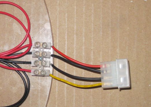
Connect the 4
peltier wires to the terminal block/connector of your choice. Ensure
that you know which wires are for which cell. Putting 12v onto the
'cold' peltier and 5v onto the hot peltier will result in an
interesting, if not fatal, thermal condition in the stack.
Gently fit the
polystyrene base insulation over the stack. Ideally the coldplate will
be about 0.5 to 1mm above the surface of the base. If much higher add
layers of 2...3mm foam under the polystyrene - cut a cold plate sized
hole in the foam sheet - no need to dismantle the whole stack.
If the coldplate is below the level of the polystyrene base - review your
measurements! There are 3 options: First option: Remove the bottom layer of
2...3mm insulation - cut it around the foam coldplate insulation, do not
pull it out as this will change the pressures within the peltier stack
and may loosen the insulation foam.
Second option: Dismantle the peltier stack and use a larger spacer block.
Third option: Use thinner polystyrene sheet for the base insulation - do
not go below 15mm or thermal performance will be degraded.
The system can
now be tested for operation.
It is wise to check the peltiers before
applying full power for any more than a few seconds. With a current
meter in circuit apply 5 volts to each peltier in turn for just a second
or two. Ensure the current is about 1.8...2 amps in each cell.
If at 5 volts both cells currents look good, apply 12 volts to the lower (hot) cell.
Ensure the current is in the 4...5 amp range for a 1206. The coldplate should
noticeably cool down even in just a few seconds
If the hot cell and cold cell currents are in range, connect the hot
cell to 12 volt supply, the upper (cold) cell to a 5 volt supply and
switch the power on for a moment (no more than a few seconds). The coldplate should be noticeably cold and the heatsink warm. If so - it's
working.
Note: Do not run the stack for more than a few seconds without
watercooling the heatsink. Over 60 Watts are being dissipated and the
heatsink will warm up very quickly.
Fit the fence.
The fence should slide snugly between the coldplate and
the polystyrene insulation. Gently work it in so that the fence is an
even 5mm or so above the coldplate all round. The overlap must be at one
short end to improve viewing/lighting.
It should slide down until it meets the foam insulation below the
coldplate. Take care not to damage the fine temp' probe wires if
installed.
Water cooling.
Any suitable container will suffice. What is suitable will depend upon
the dimensions of your base plate. As described
here, this system
running with 2 x 1206 peltiers at 12v and 5v heats water at about 1C per
Litre per minute. So 15 litres will heat up at the rate of 4C per hour.
A flat sided container is preferred since you will be able to mount
the water pump directly to the side. A small/medium aquarium
is ideal, although a basic bucket, large paint container, almost
anything watertight and suitable dimensions could be
used.
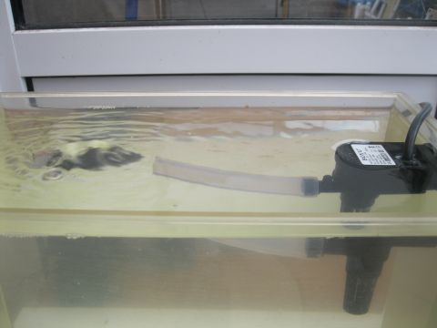
Fit the plastic 15...20mm tube over the exit pipe of the pump and
arrange it so that the water flows directly through the fins under the
peltier cells and washes along the flat surface between the fins, see
here. and pic' on
left - water forms a 'bulge' where the heatsink would be, 'washing'
along the heatsink base plate between the fins.
Fuel supply.
Cloud chambers will work with almost any low boiling point solvent,
I have even had this one working with water, although the results are indistinct and the coldplate soon forms into a frost garden, see
here.
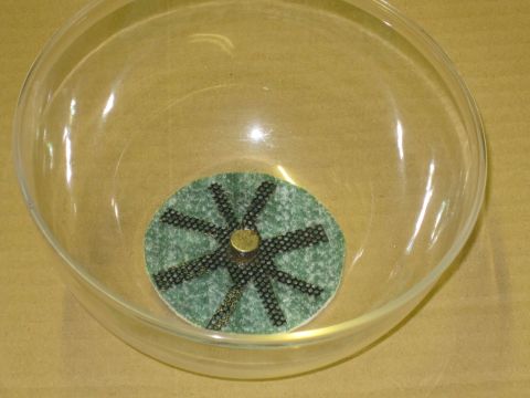
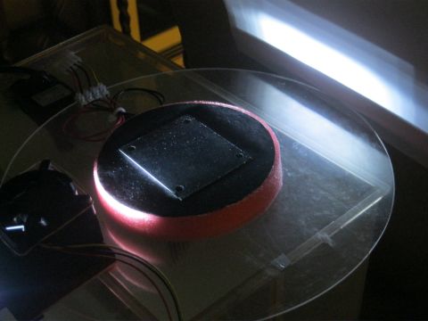
The fuel supply is stored in a felt pad held at the top of the
chamber by magnets (one on the steel 'star' the other outside the
container).
Cut a disk of felt about the same size as the flat(ish) base of your
bowl (dome), or about 5cm. I made a 'star' (perforated steel, old front
cover panel from a PC) to ensure the felt is
pinned to the top of the dome- see pic - this helps with heat transfer
and slows the cooling of the fuel supply. If the felt/fuel overcool they
stop producing sufficient vapour for clear operation of the system.
I often use a reel of solder as a 'gentle' heat source to stop the
fuel overcooling. If the felt was 'loose' of the top of the dome then
the heat transfer to the fuel would be very limited and the system stop
working very quickly at low running temperatures.
If you are only building a basic unit (no optional ion scrubber,
fans, lamp power etc) then you are ready to start
running your cloud
chamber.
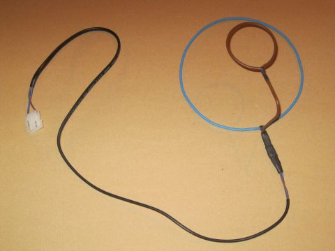
Ion scrubber,
optional. A pair of wire loops that fit over the dome.
Make insulated
wire loops from the solid cores of some 'ring main' cable. Larger loop
fits easily over the base of the dome, the smaller loop is about the
size of the flat(ish) base of the bowl (dome). The small loop is held in
position over the dome by extending the wire from the loop over and bent
down straight to the insulated connections. the loop terminations are
crimped/soldered together then insulated with minimum 2 layers.
The connections of the solid conductors to the double insulated mains
cable must be individually insulated then sleeved together - heatshrink
tubing is excellent for the job. Ensure that NO BARE METAL of the
conductors is visible anywhere. These will be at high dc voltages (350
volts). The 2 x 470K / 1M resistors fitted to the
power supply
limit the short circuit current to a few hundred microamps so it should
not be more than a minor jolt - but why risk it - INSULATE well.
I used a power supply extension plug to connect the cable to the high
voltage output described in the 'Electronics'
section. Removing all pins from plug and socket and reconnecting and
re-inserting only the outer two to the high voltage lines.
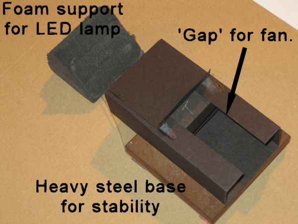
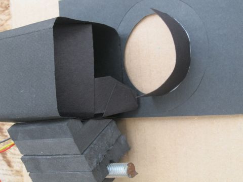
LED Light shroud.
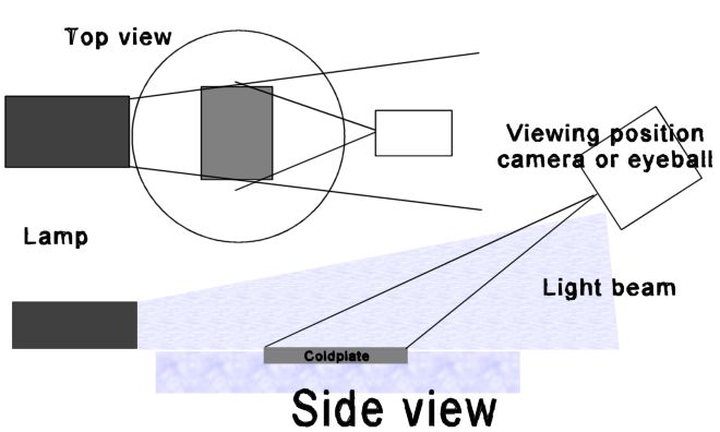
The lighting of a cloud
chamber to get the best viewing results is critical. Many online designs
show the lamp at 90 degrees to the viewing angle - this works but is by
no means the best angle. The best views are achieved when the light and
the viewing angle are almost coincident - see diagram below and
Videos, Pictures and explanations
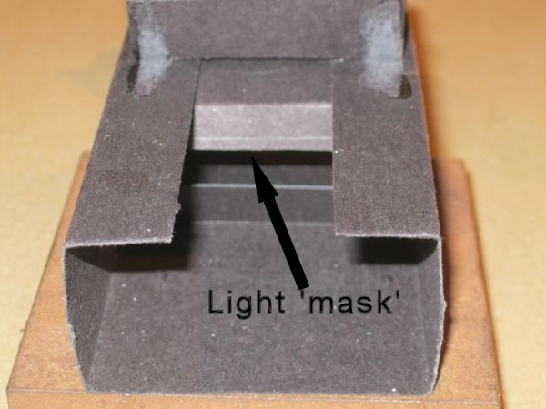
However to achieve so close an angle of view to the light source the
light must be masked to form a reasonably confined beam - see pics'
left. This is why a LED lamp with a line of LED's is better than a lamp
with a circular cluster.
Make a card tube that fits over the lamp you use.
Create a mask with a rectangular hole that can be slid up and down the
tube. The exact dimensions of the tube and mask will need fine tuning to
get the best illumination.
Position the tube and lamp at the edge of the polystyrene base and
using foam blocks or similar adjust the height of the lamp so that the
beam just 'skims' the surface of the card on top of the polystyrene.
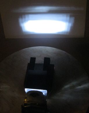
Adjust the mask so that the beam just covers the coldplate at its
widest and 'skims' over the surface. Any dust or debris will be clearly
visible when the light is skimming the coldplate surface, see image
below.
Adjustment of this light takes time - but it is truly worth it. The
difference in good and poor lighting can be seen
here. Pic below
clearly shows dust and debris on the plate all the way across.
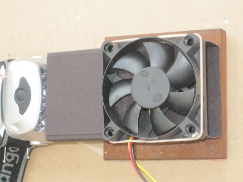
I fitted
fans to the light and viewing areas since I wanted to mainly image and
video the chamber, demisting the windows every few minutes is a pain!
Viewing window fan. Using the black card make a box that fits around
one fan. Fix the fan into one end - ensuring the airflow is into the
box. Place inside a deflector panel to push the airflow towards the dome
surface. Cut a 'viewing window' into another piece of card and fix to
the dome side of the fan box so that the airflow out of the fan washes
across the 'window'. See pic' on left. Improved de-misting is achieved
by fitting a 'fence' around the window to confine the ariflow as seen in
pic.
Lamp fan. Take the lamp shroud made above
and remove a section of the top the same length as the fan, obstructing
half the fan as seen in the pic's is not a problem: Minimal, but
sufficient, airflow is the aim. Fit the fan to cover this hole, airflow
into the shroud. The air will then flow out of the end of the shroud and
(if the shroud is mounted close to the dome) wash directly onto the dome
only in the area of the light entry point. The position of this fan
limits the range of positions the sliding light mask can take. Ensure
that you shape a mask that works when it is 'behind' the fan.
It may seem OTT to keep the airflow from washing over more of the
dome but the outside air is a significant (if not the most significant)
source of heat leakage into the chamber. The less air that moves the
less heat is transferred. See Pictures, Videos and explanations for more info'.
How to make a CD wimshust machine
- A 9.3 minute video providing full instructions on how to make a wimshurst
machine from CD blanks and household items.
CD wimshurst
machine 1 - wimshurst machine, cobbled together in an afternoon from scraps
and a couple of CD's.
CD
winshurst machine 2
- Short video of the wimshurst machine made in the 'How to build a CD wimshurst
machine' showing max sparks of 15mm and overloads.
32cm wimshurts machine
- A short video of a wimshurst machine with 32cm disks, this produced over 130mm
sparks and is a very reliable wimshurst machine.
Cloud chamber 1 - 1
short video of an Alpha source (Am241) and background radiation in a homemade peltier
cooled cloud chamber without dry ice.
How to make a cloud chamber - a 5 minute video on how to build a simple
cloud chamber in less than an hour. How to build a cloud chamber without dry
ice, peltier cooled.