|
How to Build a CD Wimshurst machine |
||
|
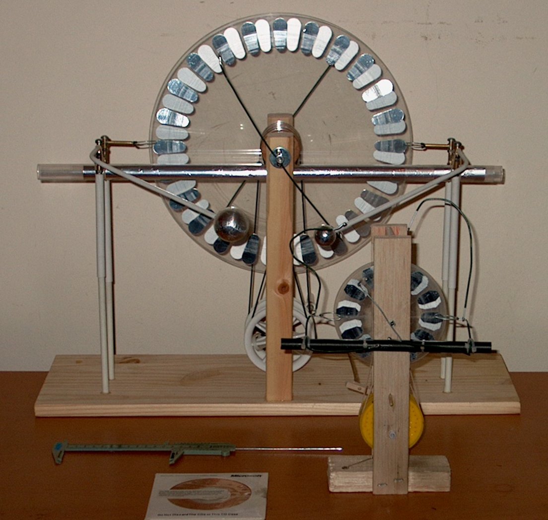
I have been asked to give more info' on how to build a CD Wimshurst machine. This 9.3 minute video covers the construction and assembly of a small WORKING CD Wimshurst machine. This machine has produced 15mm sparks - video link. |
|
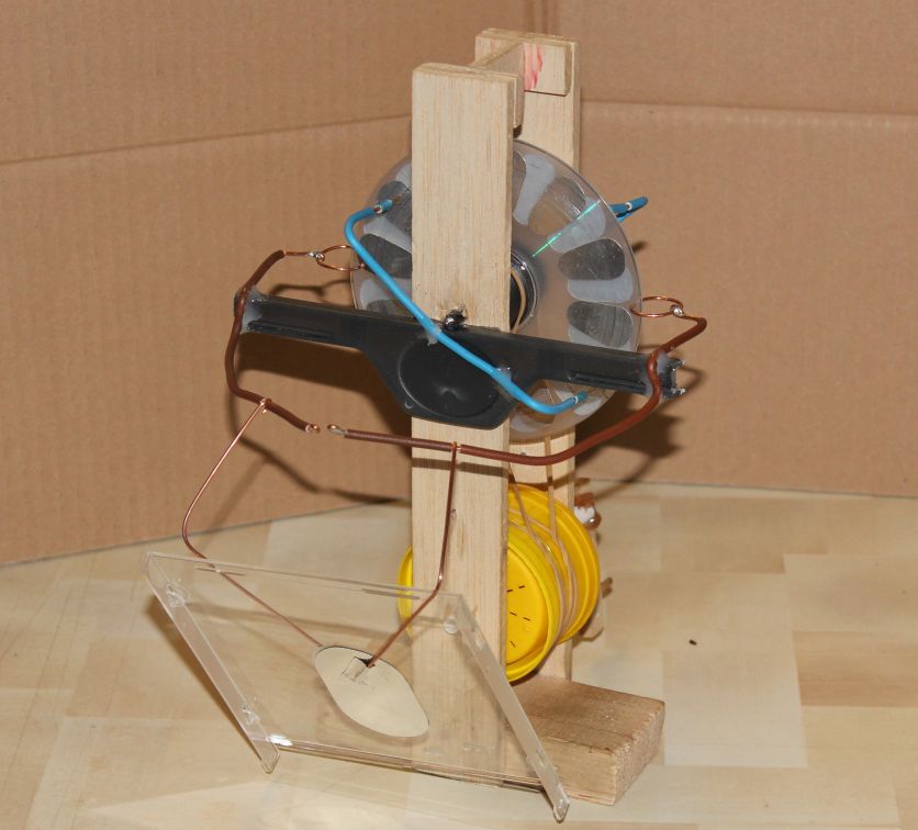
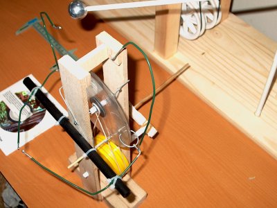
The CD Wimshurst machine from the 'How To Build a CD Wimshurst Machine' video. |
 |
||
| The machine in the How to Build a CD Wimshurst was based upon my original 'Slow Sunday' CD machine described below. It uses the same balsa wood frame. | Below are images of my original CD Wimshurst machine. | |
I built this little beastie on a slow Sunday afternoon. Just a couple of CD blanks - the "protectors" top and bottom of a CD stack. Some aluminium tape, bailing wire, coat hanger, a pair of pulleys from a dismantled CD player. Balsa wood supports, plastic pot lids as lower pulleys and a pair of elastic bands - stuff we all have (except the aluminium tape, use kitchen foil and adhesive!). CD case and kitchen foil as a storage capacitor (Leyden jar.). It worked, just about! |
 |
|
|
|
 |
|
|
Disks CD's should be as flat as possible so they rotate with as little "wobble" as possible. True for all these types of machine. With the CD's between 1...1.5mm apart and concentric reliable operation was achieved. Ideally the disks should be as close as possible without touching. However under load the electrostatic forces will draw the disks together, the higher the voltage the greater the electrostatic attraction between the disks. Sectors The sectors should be clean edged and smooth. Aluminium adhesive tape is ideal. Copper adhesive tape is less easily obtained but yet effective since it is a harder metal. Baking tray foil and contact adhesive is also a suitable substitute. The sectors should be cut in a smooth curve for best operation - any sharp edge will encourage corona losses and discharges between sectors. The CD machine uses rough cut lozenges - rectangles with cut corners - but has a low output. Any even number of sectors can be used from 8 upwards - my CD machines use 12 per disk, my 32cm uses 24 per disk, each disk must have the same number. The maximum output spark is approx' proportional to the sum of the gaps between all the sectors from the charge collector spikes to the neutraliser brushes (approx' 60 degrees). Therefore more small sectors should produce a higher output voltage and therefore longer sparks. Larger sectors typically produce more output current (for a given disk speed). If the sectors are too small then the output current may not exceed the losses in the system and therefore no useable output, starting and maintaining charge may also be adversely affected by small sectors. Varnishing over the edge of the sectors may also improve output by effectively insulating the edges of the sectors and filling in any small imperfections that may have encouraged corona discharges. See 32cm Machine images. Brushes (the biggest headache). See detail pic's. For quick and easy brushes: A few strands of copper wires from a (flexible) multi-strand wire.32x0.05 is ideal - 32 strands of 0.05mm copper. 6 strands held to the neutraliser arm by a rubber sleeve, approx' 8mm free to flex. These are OK for testing and short term operation but require constant maintenance - especially if the machine runs backwards - EM motor effect, spring in drive belts etc. I use these on the 32cm machine as it is easy to maintain and has very flat disks and sectors. For the motorised CD Wimshurst I have used brass buttons on the sectors to protect them from damage by the brushes - even soft copper brushes destroyed the aluminium sectors. The brass buttons destroy any (soft) wire brushes. I tested several items but found the best result using springs and rubber sleeves. The spring is from the "hatch" on a 3.5" floppy disk. The spring "loop" is held in the rubber sleeve to act as damper and holds the spring to the neutraliser arm. "Contact" end of the spring in bent to offer a (very) low angle of attack to the brass sector buttons. The Brushes I have on the original CD machine are now a loop of flat ribbon cable (as used to connect the optic head in a CD player to the fixed circuit board.) A single conductor is separated, cut to approx' 25mm. About 5mm of each end on one side are stripped to the conductor. The centre of the strip is stripped on the reverse side to the stripped ends - approx' 5mm. This is fixed by a rubber sleeve in a loop around the end of the neutraliser arm. This has worked reliably for several weeks without any adjustment). These are great for small (slow) machines but the very thin conductor would wear through rapidly on a fast or larger machine. Collectors A sharp spike approx' 1mm from the disk surface symmetrical both sides and fitted into the end of a 4mm brass tube. These need to be as close to the disk surface as possible (1mm is a good compromise), over the sectors. If the collector spikes touch the disk they will cause damage, so adjust carefully allowing for any disk wobble and flex and any flex in the conductor support structure. With metallic sectors on the Wimshurst machine only one spike is needed unlike in sectorless machines where the output is improved with a "comb". Conductors and their fixings On the 32cm machine and motorised CD machine all conductors are brass tubing 4 or 6mm diameter. Joints are tin (lead free) soldered. The (32cm Machine) fixing screws, 50mm M5 pan head screws, have their heads solder filled and built up then shaped to a smooth dome. All solder joints are polished to smooth curves - a sharp edge or point is corona discharge heaven. The motorised machine uses brass hex M3 pillars as fixing screws/nuts - filed and polished to cylinders, M3 pan head screws soldered and smoothed.. The original CD machine uses simple "bailing wire" - 1mm steel wire with 0.5mm insulation - joints are loops of one around another and terminal balls are small oversoldered loops. Terminal balls Any metal or metallic coated balls will do. I have foil taped a pingpong ball, used a chromed plastic bead, foil taped hand carved cork "ball". There are guidelines on the best ball size for each machine/expected spark size but I find it's more a case of "what can I use for a ball" rather than finding one the right size - they can be expensive if you can't make them! Supports etc There are many ways to build the drive mechanism and support structure: The shaft holding the disks is normally an insulator with the disks and pulleys running on bearings. I use an 8mm fibreglass rod for the 32cm machine and 22mm skateboard bearings. The CD machine uses a metal rod (from a CD drive mechanism) and 4mm brass tubing as bearings - after an upgrade from using the CD pulley hubs that were not stable!. The metal shaft connects the two neutraliser bars electrically - this does not appear to affect the operation - I tried an insulated shaft and found no difference in output. Drive shaft (motorised or hand cranked) and lower pulleys must all be insulators (plastic, fibreglass etc). Drive belts must also be insulators as they pass close to the surface of the disks - do not let them touch the disk surface. Each disk must rotate in opposite directions. I used simple rubber bands on the original CD machine, the 32cm machine uses nitrile rubber approx' 1.25mm diameter joined with superglue. One straight and one crossed to reverse the disk direction. The motorised CD does not use drive belts.. Chassis: As long as its strong and rigid and not conductive - design detail is not important. Wood is a conductor at the voltages these machines generate so the conductors must be supported on insulators at least the maximum expected spark length from any wood (or other conductive) part. Any plastic will do. There are many sites offering much more: A great site for all sorts of machines and info: coe.ufjr.br-machines Good looking machine with construction details: Steampunk Workshop How it works: coe.ufjr.br-how it works Or just Google it - there are over 30,000 sites/pages out there. Beware of the free energy sites, the laws of physics rule over all manmade fantasies! NOTE: The energy used to generate the output can be observed using this method. 1: Disconnect both neutraliser brushes but leave them in contact with the disk. If the brushes are fixed, like on my machines, then this is not possible, and the brushes must be removed from contact with the disk - one on each side. However the small amount of friction from the brushes will only minimally affect the tests if their drag is very low. Disconnect any layden jars/capacitors. 2: Spin up the machine to a known speed - no output is generated so the only losses are frictional - and measure how long it takes to stop - a good machine will spin for well over 30 seconds! 3: Re-connect the neutraliser brushes. 4: Spin the machine up to the same speed as para' 2 above ensuring the machine is generating power, it should be much harder to turn the crank to maintain the same speed. Make sure the spark gap is well beyond the maximum spark potential of the machine so the only losses are corona discharges. Now measure how long it takes to stop! NOTE: The machine may run backwards after stopping - this is the electrostatic motor effect as the charge stored in the disk and conductors is dissipated and should be avoided as it can damage the brushes! The effect is very pronounced with capacitors fitted. In para' 4 the resulting time will be much less than the unloaded spindown time in para' 2. This reduction in spindown time is a result of the electrostatic forces between the disks and the extra energy to keep the disks spinning at speed is where the power (to drive the output) comes from. Anyone who has hand cranked one of these machines is aware of the increase in loading as the charge builds up! It's possible to calculate the exact amount of power but you need a good head for figures. I have seen a reference to the formula and if I find it again I will insert a link.
|
|
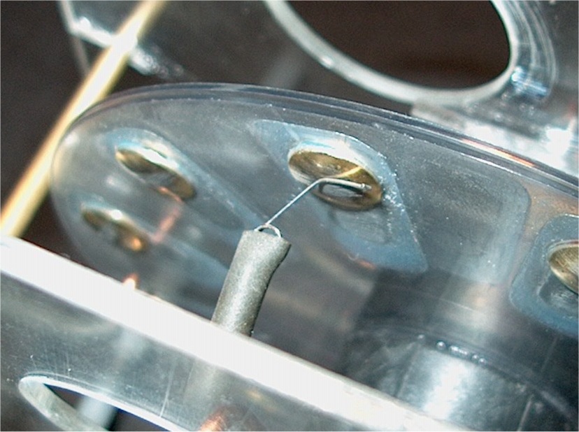
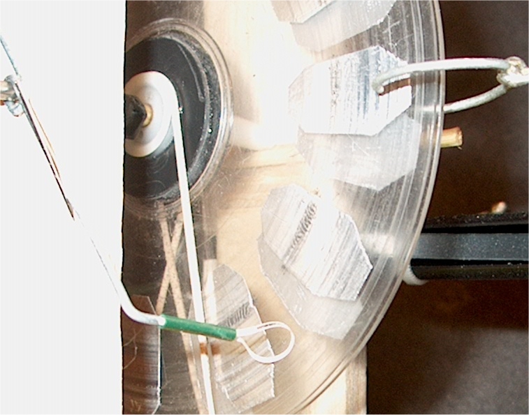 Closeup of original CD machine showing aluminium sectors - note damage from early brush experiments. Loop brush (loop of a single flat ribbon cable conductor). Bailing wire charge collectors at top right. |
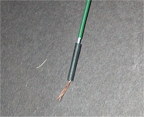 Simple copper wire brush with retaining rubber sleeve. as used on the 32cm machine.
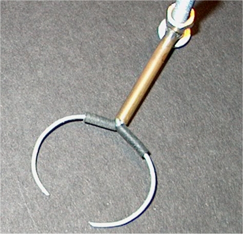
"Spring brush" and brass buttons on the motorised CD machine. |
||
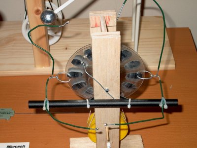
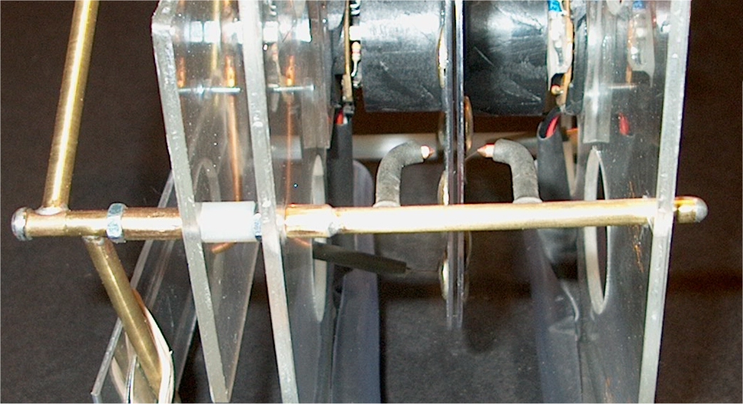 Another view of the motorised CD machine showing charge collectors with rubber sleeve insulators and brass tube conductors.
Charge collector from 32cm machine - could easily be improved with brass tube "loop" and copper wire points soldered into ends! |
||
|
---------------------------------------------------------------------------- Link to Wimshurst machine design program: wmd.exe ---------------------------------------------------------------------------- Capacitor calculator: C=ExA/D Where C = Capacitance E = Relative permitivity A = Area (Metres square) D = Separation of plates (Metres) A tube can be considered as a flat plate of approx' the same area as the inner tube plate. Therefore in the tube capacitors of the 37cm machine: Tube diameter = 32mm, Therefore approx' 100mm circumference. Length of foil section = 100mm. Tube wall thickness 1mm Therefore capacitor area = 0.1M x 0.1M = 0.01sqM Tube wall thickness = 1mm = 0.001M Tube material is "polycarbonate" with a relative permittivity of 2.5 - estimated as polystyrene / pvc have a permittivity range of 2.2...2.8 The value is relative to the permittivity of free space = 8.854x10⁻¹². Therefore: C = 2.5 x 8.854x10-12 x ( 0.01 / 0.001 ) C = 22.135x10-12 x 10 = 220pF ---------------------------------------------------------------------------- Series capacitor calculator: Equivalent Series Capacitance (Cs) = (C1 x C2) / (C1 + C2) Therefore Cs = ( 220x10-12 x 220x10-12 ) / ( 220x10-12 + 220x10-12 ) Cs = 110x10-12 = 110pF |
||
|
| ||
 |
||