| The
electronics in this project are relatively simple, and mostly
optional. The only essential for operation is connecting the 2
peltier cells to a power supply. The Ion Scrubber, LED lamp supply
and fans are all options to improve viewing and ease use - I dislike
having to replace batteries and constant wiping of the dome to get a
good view. The optional Ion scrubber, however, does require working with high DC voltages and must only be done by someone with experience of working with high voltage circuits. You have been warned, so no excuses and no winging to me about your burnt fingers and 3 days of numb tingling arms!!! |
1: DC power supply 5 and 12 volts 2: The ion scrubber (optional, the chamber does work without it) - this does require partial dismantling of the PC power supply and locating the DC high voltage used by the switchmode power supply circuits. DO NOT attempt this task if you are not experienced in working with high voltages - get someone with some knowledge of electronics and power supplies to complete this part of the project. You have been warned, don't whine to me if you get shocked! 3: LED lamp (optional, batteries work just as well) 4: Temperature probe (optional). Use much finer wire to mount the probe to prevent heat conduction through the probe wires. 5: Fans (optional)
|
|
|
|
||
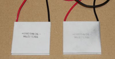 |
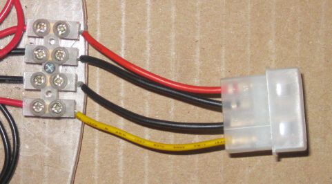
Peltier Cells: The peltier cells - these are 1206's. 1210's are the same size @ 40*40*3.5mm Red wire POSITIVE connection. Black wire the NEGATIVE connection. As shown the COLD side is facing UP. I have connected these to a terminal block. They could be soldered directly to the power supply wires, or the AX extension cable/connector described below. The 1206 Cells will draw approx' 4.5 amps at 12 volts, the 1210 cells will draw approx' 7.5 amps at 12 volts. At 5 volts the 1206 draws 1.9 amps.
|
|
 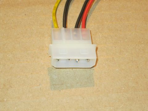 |
12 Volt and 5 Volt power
supply. PC power connector (Hard disk, DVD - pre SATA) Red wire: 5 volts Yellow wire: 12 volts Black wires: 0 volts (ground) Use both ground return wires, one for the 5 volts, the other the 12 volts. The peltier cells draw a lot of current. An AT extension cable can be used to wire to the terminal block. This allows the power supply to be unplugged from the system without disconnecting the terminals. See lower pic' on left and below. Use an extension cable with heavy duty wires, some (for fans etc) have wires too thin for the currents drawn by the peltier cells. |
|
 |
||
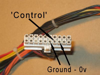 |
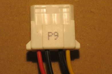
AT motherboard connector. The control pin to switch on the power supply is always as shown here on the left. The wire colour varies by manufacturer but is often listed on the power supply label. To switch on the 5 and 12 volts from the power supply connect the 'Control' pin to a Ground/0v pin. The power supply 5 and 12 volts are only on when the control pin is grounded. See warnings in the next section if you plan to use the Ion scrubber. If possible use a power supply with its own On/Off switch and permanently bridge the control pin to a ground / 0v pin. |
|
|
|
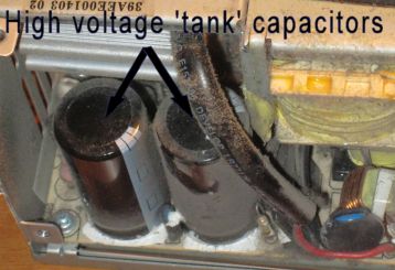
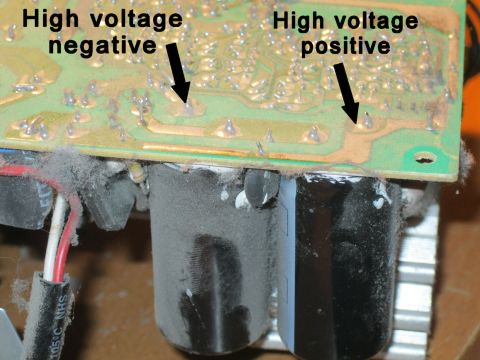
Ion Scrubber power supply
- optional. Locating the high voltage side in the PC power supply. In UK the high voltage is approx' 360 volts DC. This is the RMS voltage (240Vac) multiplied by 1.414 (sq' root of 2). In the US the high voltage will be approx' 156 volts DC. Anything over 60 V DC is potentially DANGEROUS and these power supplies the DC voltage is stored in 2 large capacitors - more than sufficient energy to kill under the right (er wrong!!) circumstances - even when the power suppy is UNPLUGGED. Please heed my warning and do not complete this OPTIONAL part of the build without suitable experience or supervision. Note that the high voltage is ON all the time the power supply is plugged into the mains supply, it is NOT controlled by the power supply control pin described in the section above. Use a power supply with it's own ON/OFF switch if possible and allow plenty of time for the high voltage to discharge before attempting to work on it. The two tank capacitors are shown in the first image on left. The circuit board has been removed - lower pic' on left - the high voltage tracks identified. Note: All manufacturers power supplies are different in design so these images are just for general guidance. These tracks can then be traced to find a suitable point to connect the two 470K or 1M 0.25W resistors. Connect one resistor to the high + 350v, and the other to the low -0 v. Use an existing component hole. The holes in these boards are normally more than large enough to slip a resistor wire through with the existing component still in place. (much easier if the solder is cleared from the hole first.) Mount the resistors on the component side of the board. Solder the other end of the resistors to double insulated mains cable, FULLY sleeve the resistors - there will be negligible power dissipation. Securely fix the mains cable to a convenient location within the power supply so the resistors do not move, and if available hot melt glue or similar the resistors in place. Run the cable out through the main cable bunch exit. |
|
 |
LED Lamp power supply
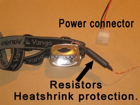
(optional) LED lamp power supply connection - optional, saves on batteries. First measure the RUNNING voltage and current consumed by the LED lamp. Most run on 3 or 4 AA/AAA cells. This equates to 3.6 or 4.8 volts unloaded. Most LED lamps run in the range of 70 to 200mA at their high setting - measure the battery voltage at the current load you intend to use. Note; Beware very bright low cost battery LED lamps. These are being run well above their recommended currents, and will overheat and burn out if run for more than a few minutes at full power. To use the 5 volts from the power supply to drive the LED lamp: Subtract the measured on load battery voltage from 5. Divide the result by the current measured. This is the ideal resistance for your lamp. ie: Batteries on load = 3.2 Volts: 5 - 3.2 = 1.8 volts Current on max brightness = 140 mA 1.8/0.14 = 13 ohms. Nearest available value: 13 ohms (E24) 15 ohms (E6). Power dissipated in a resistor = current squared * resistance = volts * current Therefore at 13 ohms LED voltage will be approx' 3.2 Volts, Current will be approx' 140mA Power = (5-3.2)*0.14 = 0.252 watts. A 0.25 watt resistor would run at over 100C at this power, so either use a high power 0.5 watt or greater resistor or, connect a few in parallel to create the ideal resistance. If similar values are used eg 3*39 0.25W creates 13 ohms at 0.75 watts. I used a bunch of old 47 and 100 ohm 0.25Ws. Connect wires to the battery terminals of the LED lamp, solder and sleeve the resistors in line with one of the wires and connect to an AT power supply plug - as used on power supply extension cables. The LED lamp will now power on when the main power supply is switched on. |
|
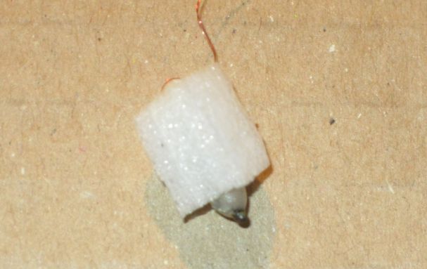 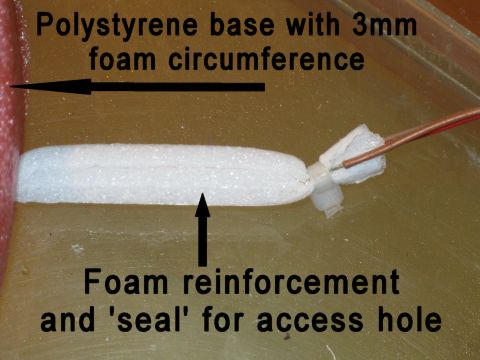 |
Temperature Probe. Modifying the temperature probe - optional - improves cooling efficiency and makes probe more accurate (much less heat conducted through the wires!) The standard probe on a digital temperature gauge is housed in a plastic and metal sleeve with a 2...3mm diameter cable connecting to the display. The large probe will mostly be in the 'warmer' air above the cold plate with only a tiny metal to metal connection on the probe tip. This configuration and the 'large' cable connection result in a miss reading of the temperature of the plate. To alleviate this error the sensor 'bead' needs to be stripped out of its metal and plastic housing, its connection wires soldered to two very fine wires - ie the wire windings from a computer heatsink fan motor. These fine wires can be run out of the system and connected to the larger standard cable from the display. In the example shown on the left I have reinforced the wires on the sensor bead with epoxy resin and set all in a foam block to ease handling. The sensor 'bead' can be set in direct contact with the plate and a small layer of 'fuel' condensation ensures a good connection. The fine wires are long enough to exit through the polystyrene base via a small (approx' 4mm) hole. The connection between the fine wires and display cable are embedded in a foam 'tube' made from the closed cell 5mm foam. This 'tube' is pushed through the 4mm hole in the base until it meets the corner of the cold plate. The fine wires and bead can then exit into the chamber via the gap where the 'fence' sits. |
|
|
Fan Power Supply The voltage required by the fans will depend upon the fans used. PC fans are either 5 or 12 volt. However if you run a fan at full power it will be far too noisy, powerful and add undesired heat to the area being demisted. I run 2 x 12 volt fans in series (6 volts each). They will not self start but once 'flicked' they run at a low speed and keep the 'windows' clear of condensation in all but most humid conditions. I have fitted shrouds around the fans to direct the flow only onto the desired spots. Details in the Assembly pages. |
||
Part 1: Shopping list and some design considerations
Part 5: Pictures, Videos and some explanations
How to make a CD wimshust machine - A 9.3 minute video providing full instructions on how to make a wimshurst machine from CD blanks and household items.
CD wimshurst machine 1 - wimshurst machine, cobbled together in an afternoon from scraps and a couple of CD's.
CD winshurst machine 2 - Short video of the wimshurst machine made in the 'How to build a CD wimshurst machine' showing max sparks of 15mm and overloads.
32cm wimshurts machine - A short video of a wimshurst machine with 32cm disks, this produced over 130mm sparks and is a very reliable wimshurst machine.
Cloud chamber 1 - 1 short video of an Alpha source (Am241) and background radiation in a homemade peltier cooled cloud chamber without dry ice.
Cloud chamber with Water as the 'fuel' - a short video demonstrating water as active vapour, very quickly frosted up! How to make a cloud chamber without dry ice.
Poorly Lit homemade cloud chamber- contrasting good and bad lighting in my homemade peltier cloud chamber! No dry ice.
Granite in a cloud chamber - no dry ice - some activity from a piece of granite. No dry ice, peltier cooled.
Background radiation in a peltier cloud chamber - no active sources anywhere near, just background radiation. Peltier cooled, homemade cloud chamber not using dry ice.
How to make a cloud chamber - a 5 minute video on how to build a simple cloud chamber in less than an hour. How to build a cloud chamber without dry ice, peltier cooled.